
SINGLE CABLE ENTRIES
WMG cable glands.
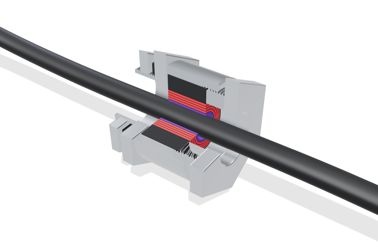
One cable, a layered fit. Two EPDM half-blocks peel layer by layer to match the cable diameter.
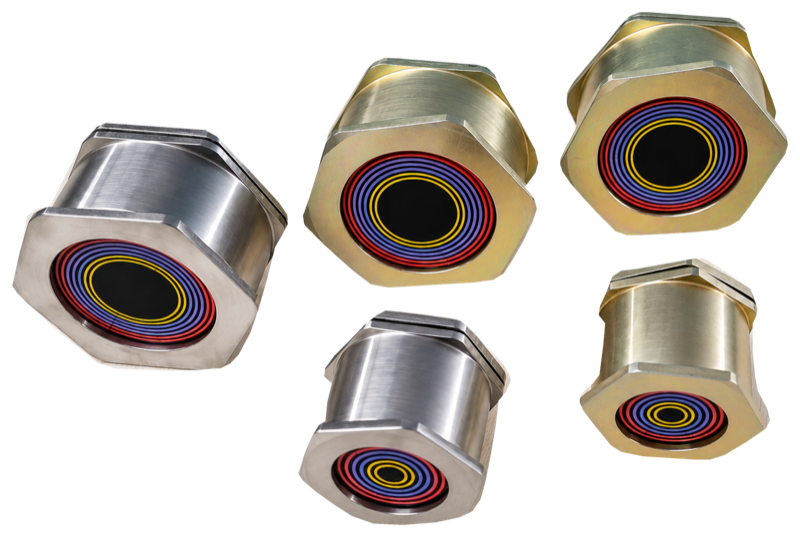
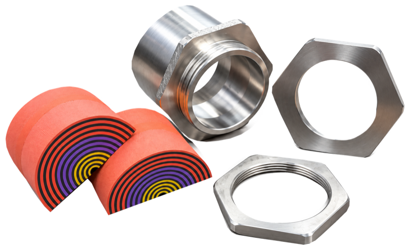
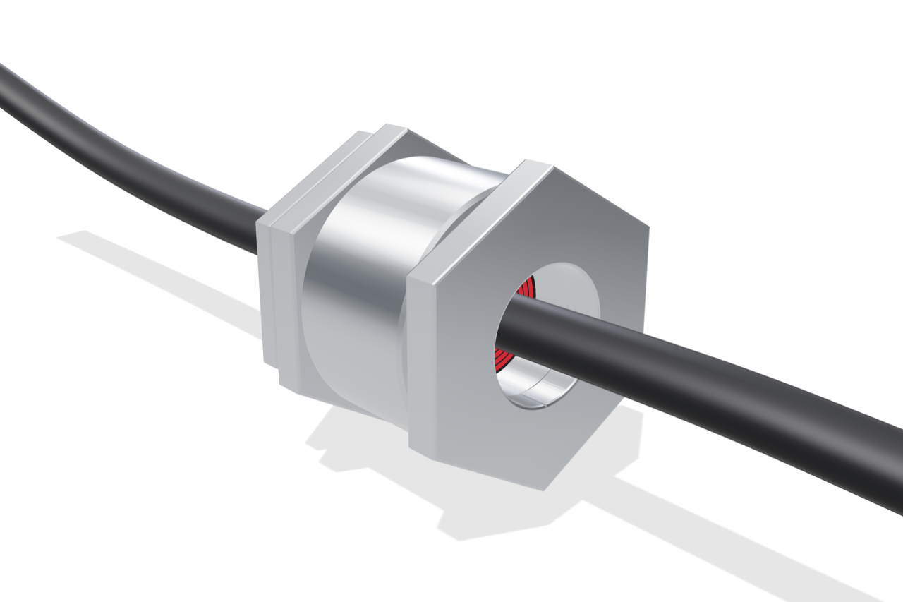
Three product views. The interactive model loads only when selected.
Drag to rotate; pinch to zoom. Use the buttons to rotate or zoom with a keyboard.
Assembled gland with the cable in place.
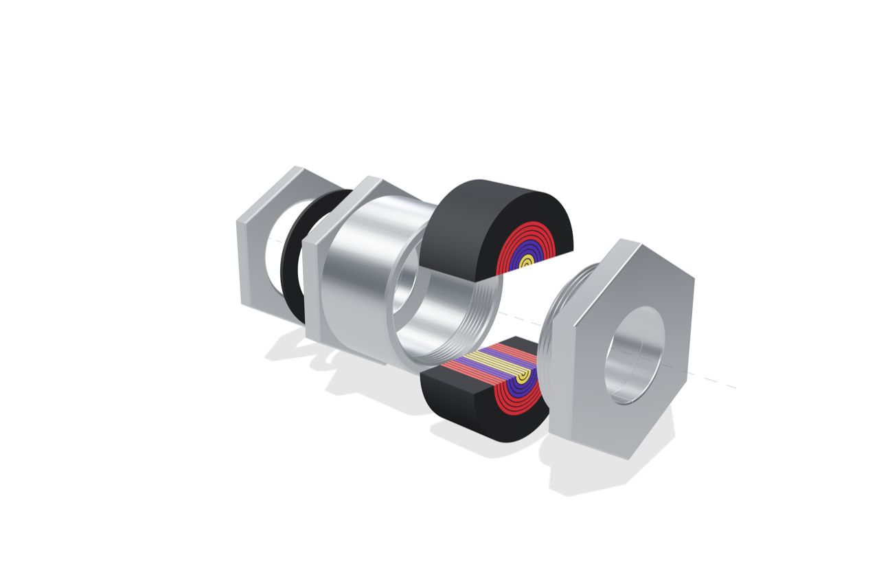
0/5 The five components, in installation order.
Five components
- Pressure pad Stainless steel
- Peel-off insert, two half-blocks EPDM
- Body Stainless steel
- Gasket EPDM
- Lock nut Stainless steel
Model geometry, layers and colours are illustrative. Use the product datasheets for dimensions and installation requirements.
Materials and cable ranges.
EPDM-based sealing rubber. Operating temperature: −60 °C to +80 °C.
| Code | Material | Size range | Cable Ø |
|---|---|---|---|
| WMGSS001 | SS 304/304L | M12–M40 | 2.0–28.0 mm |
| WMGSS002 | SS 304/304L | M50–M63 | 24.0–48.0 mm |
| WMGSS003 | SS 316/316L | M12–M40 | 2.0–28.0 mm |
| WMGSS004 | SS 316/316L | M50–M63 | 24.0–48.0 mm |
Other materials
Zinc-plated mild steel, aluminium, nickel-plated brass and polyamide (PA) are also in the WMG range.
| Material | Code | Cable Ø |
|---|---|---|
| Zinc-plated mild steel | WMGMS001 | 2.0–28.0 mm |
| WMGMS002 | 24.0–48.0 mm | |
| Aluminium | WMGAL001 | 2.0–28.0 mm |
| WMGAL002 | 24.0–48.0 mm | |
| Nickel-plated brass | WMGBR001 | 2.0–28.0 mm |
| Polyamide (PA) | WMGPL001 | 2.0–28.0 mm |
| WMGPL002 | 24.0–48.0 mm |
Product datasheets.
Dimensioned drawings for the M12–M40 versions, covering cables Ø2.0–28.0 mm.
- WMGSS001 · Stainless steel 304/304L PDF · opens in a new tab
- WMGBR001 · Nickel-plated brass PDF · opens in a new tab
- WMGAL001 · Aluminium PDF · opens in a new tab
- WMGMS001 · Zinc-plated mild steel PDF · opens in a new tab
How the gland is assembled
- Fix the body in the plate cut-out with the gasket and secure it from the opposite side with the lock nut.
- Open the two half-blocks, remove the central core and peel layers one at a time to match the cable.
- Pass the cable through the pressure pad and the body.
- Lubricate the insert.
- Close the two half-blocks around the cable and place the insert in the body.
- Tighten the pressure pad clockwise to compress the insert.
Assembly overview. Confirm the selected gland and installation requirements with WallMax®.